Toyota 2JZ-GE via Proteus rusEFI
rusEFI, Proteus, Toyota 2JZ
After much tinkering, I’m at last well on my way to converting my 2JZ powered sedan with open-source: rusEFI on Proteus! rusEFI is a GPLv3 licensed engine management solution built upon the real-time operating system ChibiOS and has a small, knowledgable, and welcoming following.
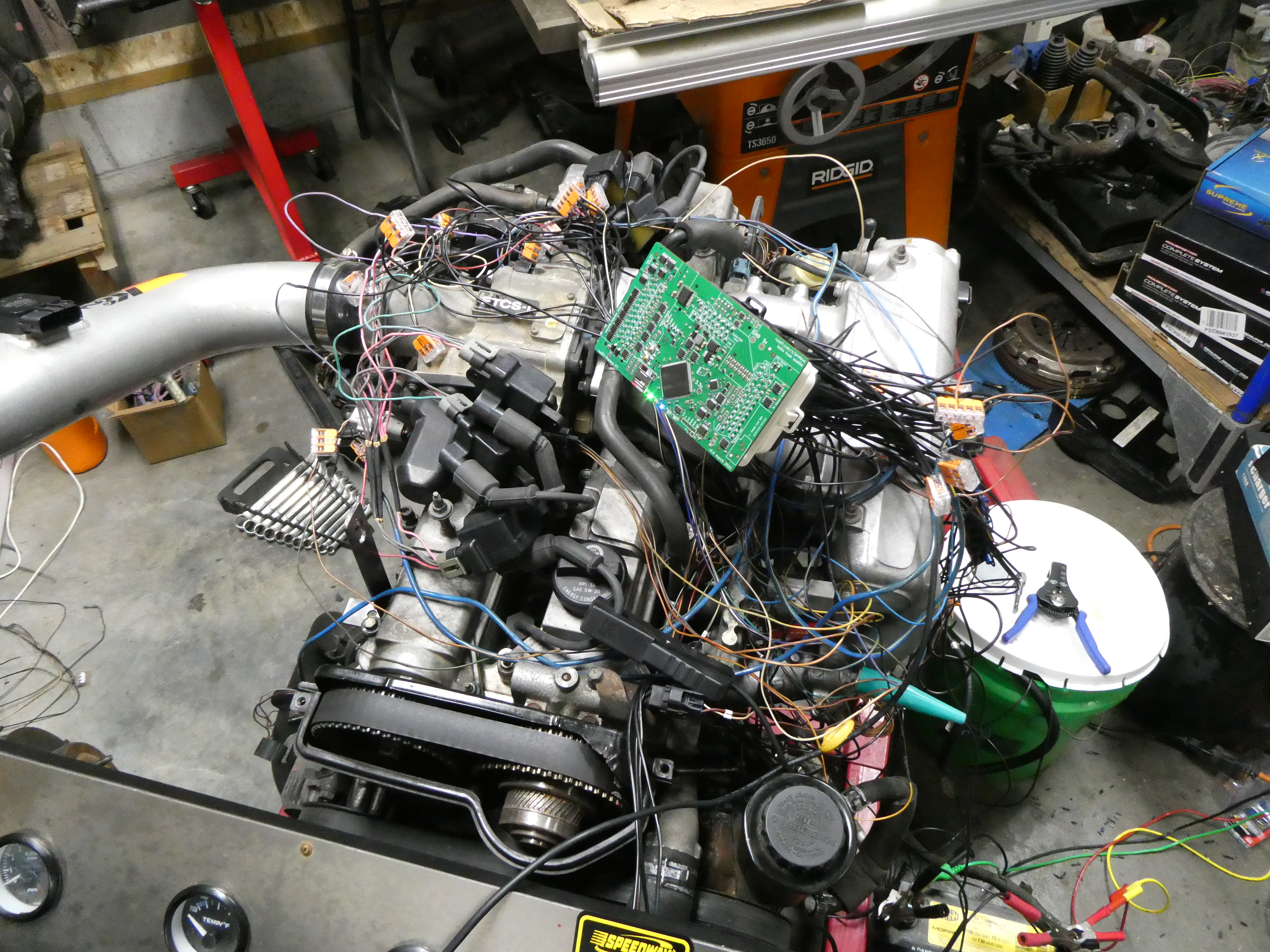
While there are other FOSS engine management solutions, like Speeduino, rusEFI caught my attention best, seeming more “professional” (and capable, if more raw) and in-line with my initial aspirations of devising a RISC-V based solution with the likes of Pine64’s Ox64. Of the many hardware platforms (“boards”) to choose from, I landed on Proteus by guidance, in that it has much I/O support and exceeds my six cylinder needs, supporting e.g. up to a fully sequential V12 engine. Proteus is designed and maintained by one Matthew Kennedy hailing Seattle, WA, but powers engines across the globe.
With the hardware in hand, I ordered some extra leaded connectors to begin the trials, saving the connector and pin kit for the final build. My first attempts at understanding were against the Toyota MAF and IAT sensor: this was a breeze, using TunerStudio MS Lite by EFI Analytics. Many alligator clips, an oscilloscope, and an STM32 programmer/debugger (STLINK-V3MINIE) later, I began tackling the Toyota ETCS-i ETB.
Toyota ETCS-i
The Toyota ETCS-i wasn’t entirely readily supported by rusEFI, though it was capable with existing logic. Mainly, the throttle position and accelerator pedal position sensors are not “typical,” in that the ETCS-i uses a dual mechanism that is not fully redundant in the honest sense: the second element does not transient the entire range of the first for both the TPS and APPS. rusEFI provides a configuration it labels as “experimental” for this mode with the TPS where it elides its redundancy conditions in the specified range (dubbed “Redundant Ford TPS”); this was extended to the APPS. The implementation is different from Toyota’s, in that rusEFI averages the two element values but Toyota uses the first directly and checks it against the second; I have work-in-progress to enable this behavior in rusEFI, which smooths small piecewise jumps across the averaging transition point (caused by rusEFI’s averaging mode).
Additionally, the ETCS-i incorporates a magnetic clutch to disconnect the throttle motor from the plate, as a safety feature. Currently, I drive the clutch via a general purpose PWM output from Proteus at 240 Hz with continuous 50% duty whenever the ignition is on. I plan to improve this later but this suffices for now; many ETBs don’t incorporate such a clutch mechanism.
The factory service manuals are invaluable, especially the Diagnostics chapter and Electrical Wiring Diagram manual. However, they’re not perfectly accurate and not directly transferrable: a good example is the throttle motor connection, which while labeled “+” and “-“, must be reversed for proper rusEFI control.
rusEFI provides an auto-calibration process for the TPS and APPS setup, as well as an automatic PID tuning mechanism for controlling the ETB. Also important is setting the ETB bias curve, which accounts for the natural position of the throttle plate when the ETB is not in command; the default bias curve required little adjustment in my case. I may expand or detail this adjustment process in a later write-up.
Crankshaft and Camshaft Position Sensors, VVT-i
The 2JZ uses variable reluctance sensors for the crankshaft and camshaft position, though commonly these are exchanged for hall effect sensors. Proteus supports two VR sensors and six hall effect sensors; hall effects are simpler to setup and use, as they are non-polarized (can be connected either direction) and provide a single-ended digital signal, whereas VR sensors provide an analog signal that must be processed/filtered and polarity matters.
To setup rusEFIs triggering mechanisms1, the offset (from TDC) of the missing teeth on the crankshaft reluctor wheel must be determined, ideally with a timing light. Setting a fixed ignition timing advance in rusEFI and dry firing the ignition (no fueling) allows to dial in this angle and determine the correct value. Removing the spark plugs allows the engine to turn more freely (i.e. faster, without resistance from compression) to aid the process. I determined a value of around 160° with the stock setup as used in the Lexus IS300.
I haven’t yet configured the intake camshaft sensor nor considered VVT-i, as this isn’t necessary to run the engine. In fact, only a single timing sensor is critical to getting a typical engine running with rusEFI. However, when using the camshaft position sensor, the relative timing/angle to the crankshaft position must be configured as well. This can be determined with properly signalling senors by using the High Speed Logger in TunerStudio, and setting the VVT bank offset value. The rusEFI Wiki notes that VVT setup is one of the more confusing aspects of rusEFI currently2, primarily in that it conflates VVT with simple sensing, even if there is no VVT in use. I believe rusEFI supports dual VVT, on both intake and exhaust, and up to two banks each, with configurable offsets for all four; the 2JZ has only VVT on the intake camshaft, of course.
Ignition and Injectors
The 2JZ-GE as found in the IS300 utilizes a wasted spark “coil on plug” ignition setup, with “dumb,” igniter-less coils and an igniter module. It also expects an ignition feedback signal to drive tachometer on the cluster. I decided to skip this, and swap to individual ignition coils; currently I’m using ACDelco D581 LS “square” coils commonly found in GM pickups and SUVs, because I need to clear the back-over intake manifold that provides little clearance to the plug valley between the valve covers. The D585 (“LQ9/LS2”, “round w/ heatsink”) GM coils will not clear the manifold, nor will the Toyota 1NZ/1ZZ (Yaris/Prius; Denso/Bosch) coils; the D585 coils will fit snugly under the manifold with the shorter boots of the 1NZ coils leaving no room for the electrical connector. Later, with my hopes for forced induction, I’ll swap to the D585 or 1NZ coils, both of which are COP without spark plug wires.
rusEFI provides a bench test interface for individual cylinder ignition as well as fuel injection; this is handy to ensure functioning coils and correct wiring and I/O setup. Definitely use this before proceeding to start the engine for the first time after completing wiring. I haven’t yet altered ignition dwell; the default value of 4 ms is suitable this far, but can be mapped according to RPM.
Wiring injectors was trivial as with the ignition coils: just a single output connected to Proteus per cylinder, configured in rusEFI, and tested with the bench test interface. The OEM injectors are about 250 cm³/min according to various Internet sources. rusEFI allows to control the dead time in accordance with supply voltage.
MAF vs MAP
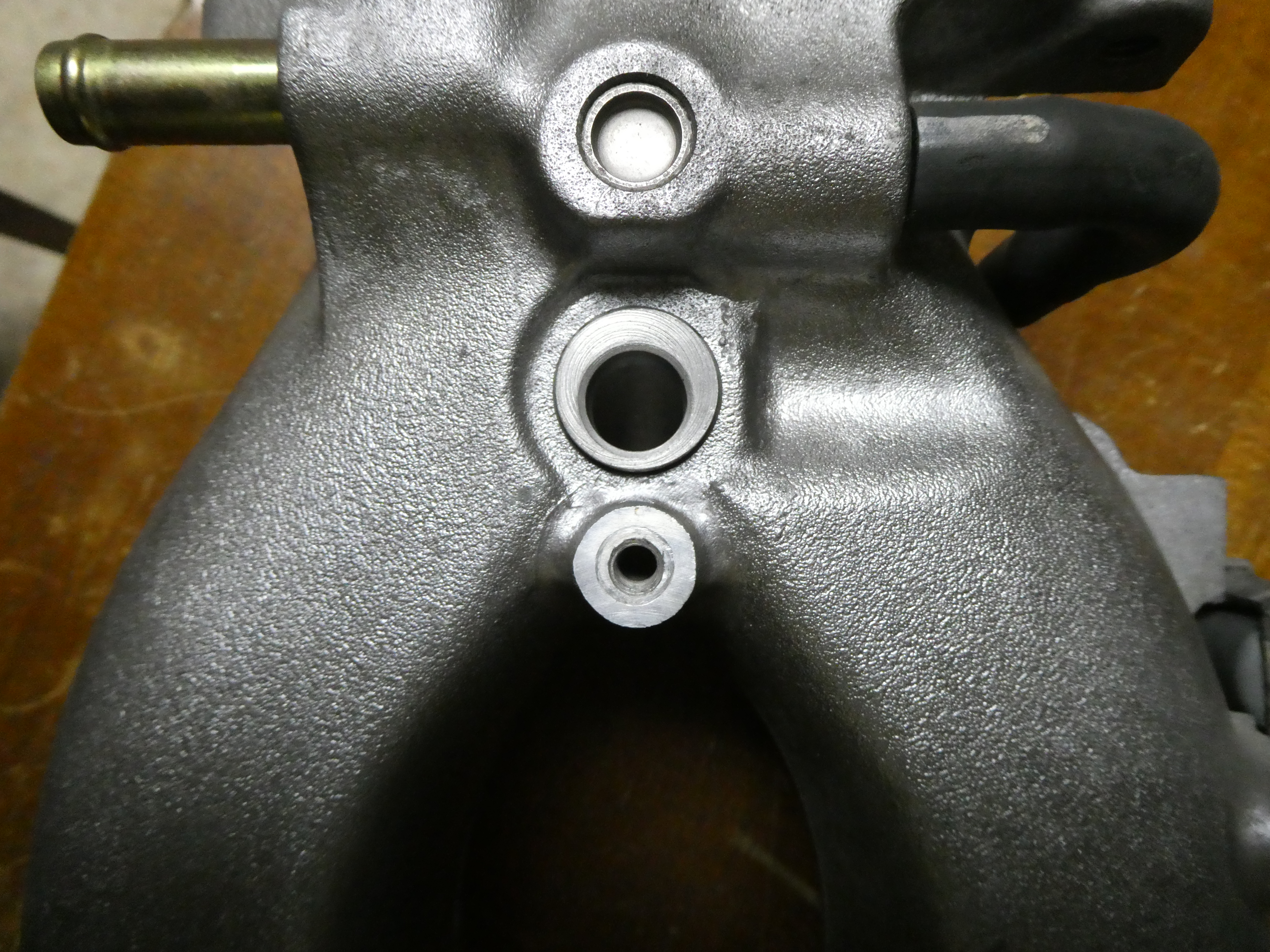
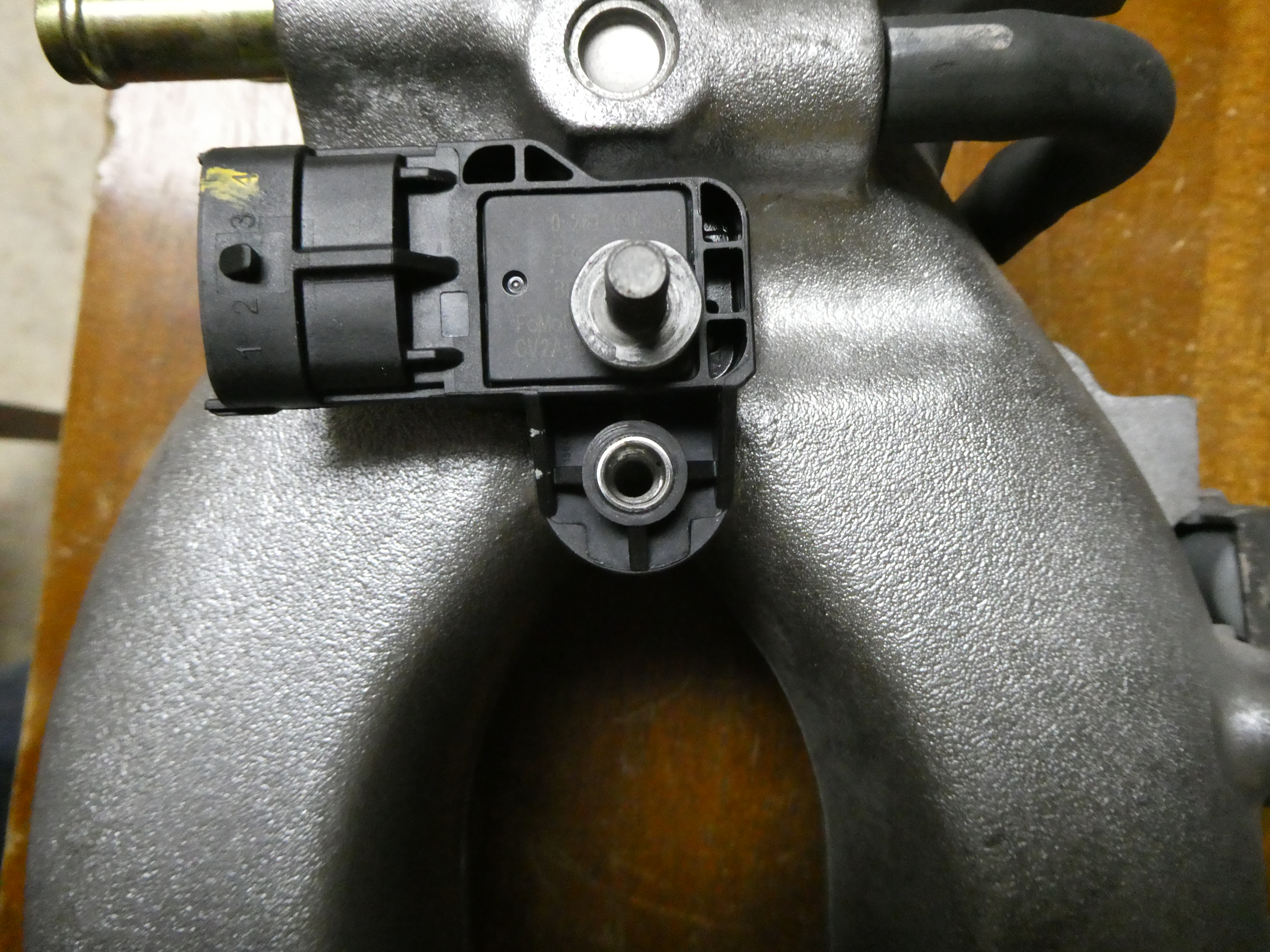
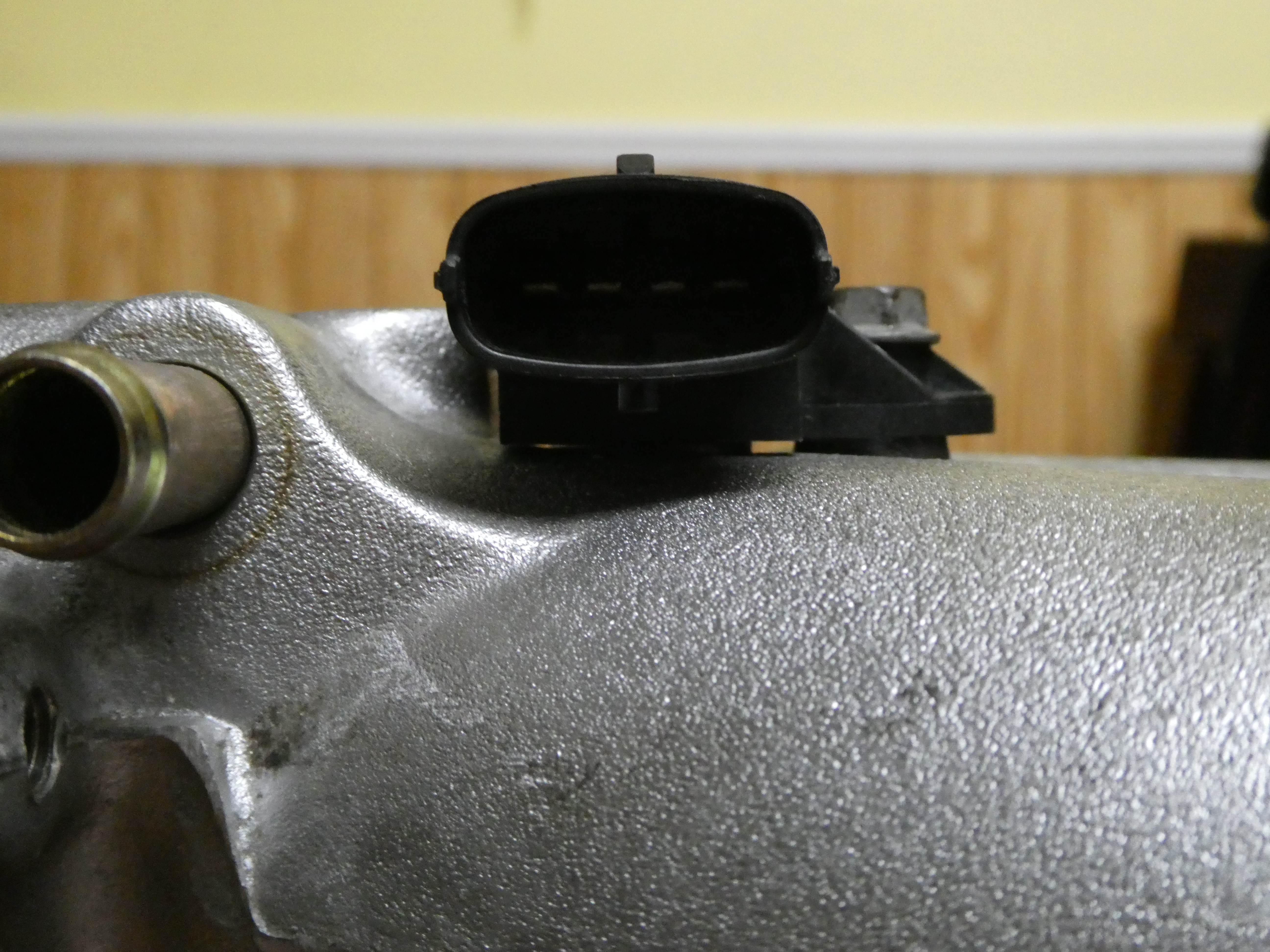
The stock engine uses a combined MAF+IAT sensor after the air filter, but I chose to switch to a pressure sensor, in preparation for forced induction. While the stock intake manifold won’t be used then, I needed to find a way to affix a MAP sensor, and also to measure air temperature. I settled on a Bosch TMAP (MAP w/ built-in temperature sensor), commonly used in Ford boosted applications among others, because they’re cheap and reliable and well documented. I found that the PCV port in the wye-manifold was in a great location and would allow to avoid modifying anything, by simply rerouting the PCV hose to tee into the manifold with the EVAP purge hose (connected to the VSV for EVAP). The port is 2 cm in diameter, and the TMAP calls for a 1.205 cm port, so I turned a simple aluminum bush to be affixed with sleeve retaining compound allowing later removal; the bolt and threaded boss are reused.
Fueling, Ignition, Starting, etc.
Initially I was very concerned about a fueling solution, considering buying an inline pump, filters, and pressure regulator. This was going to be very expensive for something I was only going to use for testing on an non-loadable run-stand, a few hundred dollars when avoiding the cheapest of the cheap when considering all of the connectors and lengths of hose I’d need to plumb everything. In the end, I simply placed the stock fuel pump in a lidded bucket and connected it to the hard fuel line from the fuel rail with a length of soft hose. I chose to drive the pump via a relay (one of the IS300 relays from the fuse block, actually) switched by one of the Proteus low-side drivers powered from the EFI relay, which cost in the end but a few dollars and works well.
The mentioned EFI relay (also from the IS300) is also controlled by a low-side driver on Proteus which are both powered by the ignition switch on the run stand. Proteus will power on with this power, or supplied USB power, and slightly alters its behavior depending which source comes online first (primarily, in the way of the SD card, affecting SD card logging, but providing a useful interface for tuning).
I chose to put the starter on a relay as well, controlled by the ignition switch and the momentary starter switch on the run stand. I have not connected this to rusEFI/Proteus yet, though there are mechanisms there as well.
In the end, I used quite a bit of wire (about 100 ft), starting with a de-loomed harness from a Lexus SC300 to provide most/all of the connectors. 3- and 5- terminal Wago connectors were also very handy, as was a terminal block to provide grounding connections, though many of the wire extensions and splices were soldered and wrapped in heat shrink tube.
Next Steps
Well, now what? Many things remain as far as engine control goes, including evaporative emissions, VVT-i, oil pressure and temperature, knock, radiator fans, alternator/charging, A/C, and power steering. Mainly though, important to closed loop control, is the emissions and oxygen sensing: I have not attached the exhaust manifold nor HO2S. I may do this on the run stand, but likely not, as the run stand cannot be loaded, and there’s not much to gain as far as tuning goes with this setup.
So, next, I plan to begin tearing down some other 2JZ motors and rebuilding them: one rebuilt to stock, and another with turbo forced induction in mind. They will be thoroughly stripped and cleaned, painted and coated, blueprinted and rebuilt. As they’re -GE blocks, I plan to drill them to open the turbo feed gallery and tap the oil feed ports, which I hope is as easy as it sounds.
Stay tuned!
P.S. Kudos to the rusEFI community and others past and present for all of their efforts. It’s exhilerating to be combining my passions for free software, electronics, and automotive engineering and seeing realized a solution I’ve long dreamed of creating.